Global’s Reliability team performs mill shell mapping and trunnion thickness measurements. This program will satisfy insurance requirements plus providing the maintenance team valuable information on the integrity of the mill components.
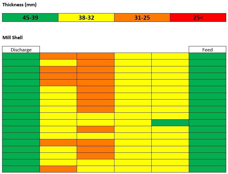
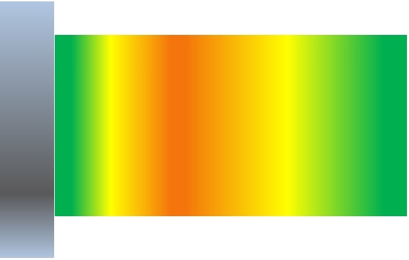
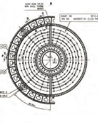
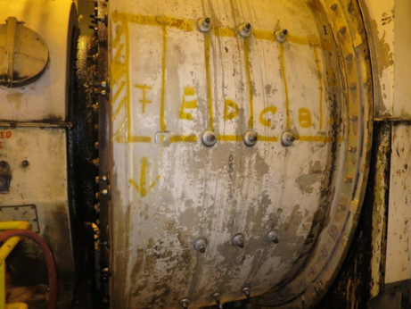
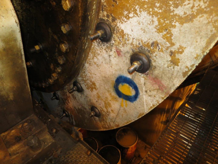
The Mill Shell Corrosion Mapping Program utilizes its Rapid Scan Technology™ to find the minimum thickness in a given area. The mill is usually separated into rows and columns using the liner bolts as a guide. Each of these quadrants are entirely scanned with RST™ and the minimum thickness will be recorded. If there is an area with excessive wall loss, this area will be mapped and marked out on the mill shell as well as in the report. The information will be plotted in an excel sheet and this will also correlate with a colour scale so that the problem areas can be easily identified.
Mill Shell Corrosion Mapping – Excel Example
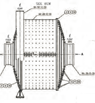
NOTE: We require original thickness and grade of material for the shell and heads. Sometimes the heads are made of extremely coarse materials such as ductile iron, making thickness inspections difficult. 250 RMS surface finish is required for good ultrasonic inspections, on mill heads we may buff spots to obtain the required surface finish for spot inspections.
Shell must be clean with no loose debris on it. The system requires a constant supply of water. Pressure washing may be required. More area can be scanned at the request of the customer.
Surface Crack Detection
Global can provide an optional surface inspection on the mill shell, construction welds, and heat affected zones of the welds. Global’s process is up to 70% faster than MPI/LPI inspection methods. This process will identify cracks that may go unnoticed by visual inspection.
This method provides real-time mapping of the inspected region, facilitating data interpretation, improving reliability, and Probability of Detection (POD).
It includes the detection and sizing of surface-breaking cracks on the shell and joints, accommodating for nonmagnetic, and non-conductive coating up to 5 mm thick (typical) between the sensor and the joint. The process covers a variety of cracking defects, such as fatigue cracks and other types of planar discontinuities at various locations in the weld (heat-affected zone, toe area, and weld cap, for example). It covers the length and depth sizing of such surface-breaking discontinuities. This process can be used for flush-ground and not flush-ground welds.
Mill shell must be clean with no loose debris on it. Pressure washing may be required.
NOTES:
The hours quoted for the inspection can be reduced if the following can be achieved;
- We require original thickness and grade of material for the shell and heads. Sometimes the heads are made of extremely coarse materials, making thickness inspections difficult. 250 RMS surface finish is required for good ultrasonic inspections, on mill heads we may buff spots to obtain the required surface finish for spot inspections.
- Shell and heads must be cleaned with no loose debris attached to the surfaces. Pressure washing might be required. A constant supply of water is required for the mill scan shell scanning.
- Global technicians must have free and easy access to the inspection areas.
- Mill is required to be turned fairly regularly.